
Page 10 - June-Month
P. 10
TECHNICAL PAPER
220 10
As- uiltb
200 9
FRP- trengtheneds
er Hydraulic Jack (kN) 180 Deflection (mm) 6 5 7
8
160
140
120
100
p 80 4 3
Load 60 As- uiltredictionb p 2
As- uilt xperimentalb
e
40
FRP trengthened rediction-s p
20 1
FRP trengthened xperimental-s e
0 0
0 1 2 3 4 5 6 7 8 9 10 24 36 48 60 72 84 96 102 114 136 160 184 196
Vertical Deflection of Overhang (mm) Load per Hydraulic Jack (kN)
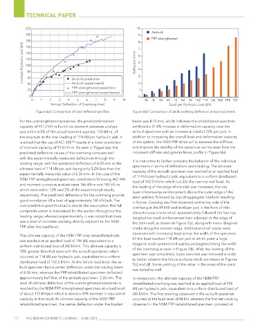
Figure 6(a): Comparison of load-deflection profiles Figure 6(b): Comparison of deck overhang deflection at key load levels
For the unstrengthened specimen, the predicted moment beam was 8.73 mm, which indicates the rehabilitated specimen
capacity of 117.2 kN-m found via moment curvature analysis exhibited a 31.8% increase in deformation capacity over the
was within 6.5% of the actual moment applied, 110 kN-m, of as-built specimen with an increase in load of 72% per jack. In
the structure at the max loading of 114 kN per hydraulic jack. It addition to increasing the overall load and deformation capacity
is noted that the use of ACI 318 [16] results in a lower prediction of the system, the NSM FRP strips act to increase the stiffness
of moment capacity of 97.0 kN-m. As seen in Figure 6(a), the and improve the stability of the system as can be seen from the
predicted deflection values of the overhang compare well increased stiffness and greater linear profile in Figure 6(a).
with the experimentally measured deflections through the
loading range, with the predicted deflection of 6.03 mm at the It is instructive to further compare the behavior of the individual
specimens in terms of deflections and cracking. The ultimate
ultimate load of 114 kN per jack being only 5.2% less than the
experimentally measured value of 6.36 mm. In the case of the capacity of the as-built specimen was reached at an applied load
of 114 kN per hydraulic jack, equivalent to a uniform distributed
NSM FRP-strengthened specimen, predictions following ACI 440 load of 142.5 kN/m, which is 6.33x the nominal wall load. As
and moment curvature analysis were 166 kN-m and 185 kN-m, the loading of the edge of the slab was increased, the top
which were within 12% and 2% of the experimental results, layer of transverse reinforcement above the outer edge of the
respectively. The predicted deflections for the overhang provide stem yielded, followed by loss of aggregate interlock resulting
good correlation till a load of approximately 160 kN/jack. The in failure. Cracking was first observed on the top side of the
over-prediction past this load is due to the assumption that full overhang at the 84 kN load level per jack in the form of thin
composite action is maintained for the section throughout the discontinuous cracks which approximately followed the two top
loading range, whereas experimentally, it was noted that there longitudinal steel reinforcement bars adjacent to the edge of
was a level of concrete cracking directly adjacent to the NSM the stem wall, as shown in Figure 7(a), along with minor diagonal
FRP after this load level. cracks along the exterior edge. Additional small cracks were
observed with increasing load across the width of the specimen,
The ultimate capacity of the NSM FRP strip-rehabilitated slab
was reached at an applied load of 196 kN, equivalent to a till the load reached 114 kN per jack at which point a large
uniform distributed load of 245 kN/m. This ultimate capacity is diagonal crack opened and quickly propagated along the width
78% greater than that seen with the as-built specimen, which of the overhang as seen in Figure 7(b). After the loading of the
occurred at 114 kN per hydraulic jack, equivalent to a uniform specimen was completed, loose concrete was removed in order
to better observe the failure surfaces which are shown in Figures
distributed load of 142.5 kN/m. At the failure load level, the as- 7(c) and (d). Some yielding of the rebar in the areas of the crack
built specimen had a center deflection under the loading beam was noted as well.
of 6.36 mm, whereas the FRP-rehabilitated specimen deflected
approximately half that of the as-built specimen, 3.33 mm. The In comparison, the ultimate capacity of the NSM FRP-
level of ultimate deflection of the unstrengthened specimen is rehabilitated overhang was reached at an applied load of 196
reached by the NSM FRP-strengthened specimen at a load level kN per hydraulic jack, equivalent to a uniform distributed load of
of about 170 kN/jack which is about a 49% increase in equivalent 245 kN/m. The first cracking observed in the as-built specimen
capacity at that level. At ultimate capacity of the NSM FRP- occurred at the load level of 84 kN, whereas the first set cracking
rehabilitated specimen, the center deflection under the loaded observed in the NSM FRP-rehabilitated specimen occurred at
14 THE INDIAN CONCRETE JOURNAL | JUNE 2021