
Page 6 - June-Month
P. 6
TECHNICAL PAPER
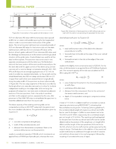
Figure 2(b): Schematic of deck specimen on left without cuts and on
Figure 2(a): Cross-section of box-girder (all dimensions in mm) right with the central cut separating the specimen for two tests
15.9 mm diameter (#5) rebar with the transverse rebar spaced detailed approach given by Equation (2)
at 203 mm on center and variable spacing for the longitudinal
rebar in order to accommodate the location of the girder (2)
stems. The remaining steel reinforcement consisted primarily of where
15.9 mm diameter (#5) rebar for the bottom slab and the stem ρ w = steel reinforcement ratio of the slab in the direction
reinforcement, with two 22.2 mm diameter (#7) rebar at the
bottom of each girder web and 9.5 mm diameter (#3) rebar used perpendicular to traffic,
for shrinkage and temperature reinforcement in the longitudinal V u = factored shear in the slab at the edge of the outer vertical
direction of the girder webs. Grade 60 steel was used for all the stem, and
steel reinforcing bars. The specimen was constructed in two M u = factored moment in the slab at the edge of the outer
separate concrete pours with the initial pour for the bottom vertical stem.
slab and the lower portion of the stems and the second pour for
the deck slab and the upper portion of the stems using cement results in the slightly more conservative result of 233 kN, for the
concrete with a nominal design compressive strength of f' c = 34.5 slab, which translates to an applied force of 116 kN per hydraulic
MPa at 28 days and an average aggregate size of 12.7 mm. In jack. The moment capacity of the slab was calculated as 97.0
[16]
order to enable two representative tests, i.e. the as-built and the kN-m using ACI 318 as
rehabilitated tests, two 203 mm deep cuts located 305 mm (12 (3)
in) apart from each other were created that ran longitudinally where
along the entire width of the specimen as shown schematically
in Figure 2(b). The two edge segments of the deck, bounded by A s = area of steel reinforcement in the direction perpendicular
the longitudinal cuts, were also removed so to allow for multiple to traffic flow,
independent loading on the edge slabs 1676 mm long. For f y = yield stress of the slab steel,
purposes of comparison, two tests were conducted on adjacent d = distance from the compression fiber to the centroid of
sections of the test specimen, first in the as-built condition the tension reinforcement, and
and then on the adjacent section, separated by the cuts, after a = depth of the equivalent rectangular compression stress
placement of the NSM FRP strips to rehabilitate the specimen to block.
meet the added demand from the sound wall.
A level of 117.2 kN-m is determined from a moment-curvature
The shear capacity of the existing overhang slab can be response calculation using RESPONSE [17] , indicating that
[16]
computed according to ACI 318 using both the general and flexural failure would govern. Following Caltrans guidelines ,
[9]
the more detailed calculations. The general calculation given by the combined dead weight of a typical sound wall and traffic
Equation (1) barrier used for bridges in California were determined to be
13.5 kN/m and 8.1 kN/m, respectively, for a combined weight
(1)
per unit length of 21.6 kN/m. The resulting total load applied
where to the specimen from the sound wall and traffic barrier can be
f c ' = concrete compressive strength (psi), determined as the product of the weight per unit length (21.6
b w = width of the concrete slab (in), and kN/m) and the length of the test specimen (1676 mm) to be
d = distance from the extreme compression fiber to the 36.2 kN, of which only the traffic barrier can be sustained by the
centroid of the tension reinforcement (in). original design. The loads due to the addition of the sound wall
would traditionally be addressed through removal of concrete
results in a predicted capacity of 236 kN, which translates to an and addition of new steel in the overhang region followed by
applied force of 118 kN per hydraulic jack, whereas the more recasting of concrete in the area of repair.
10 THE INDIAN CONCRETE JOURNAL | JUNE 2021