
Page 7 - June-Month
P. 7
TECHNICAL PAPER
Using criteria from Caltrans guidelines , the additional load Based on ACI 440 [19] , as above, and manufacturer
[9]
with a moment demand of 10.91 kN-m using the recommended recommendations that center spacing of strips should be
factor of three for new methods translates to an additional limited to no more than the lesser of 0.2 times the span length
demand of 32.7 kN-m which would need to be provided by (L) or five times the slab thickness (h), the rehabilitation design
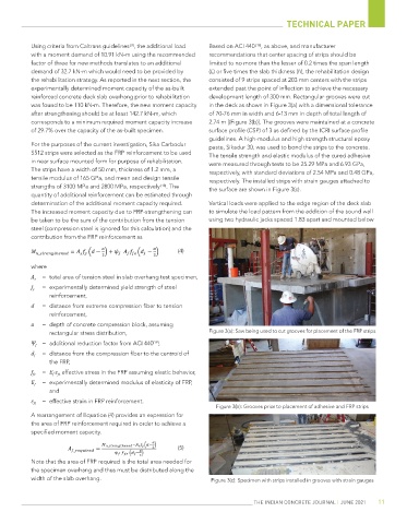
the rehabilitation strategy. As reported in the next section, the consisted of 9 strips spaced at 203 mm centers with the strips
experimentally determined moment capacity of the as-built extended past the point of inflection to achieve the necessary
reinforced concrete deck slab overhang prior to rehabilitation development length of 300 mm. Rectangular grooves were cut
was found to be 110 kN-m. Therefore, the new moment capacity in the deck as shown in Figure 3(a) with a dimensional tolerance
after strengthening should be at least 142.7 kN-m, which of 70-76 mm in width and 6-13 mm in depth of total length of
corresponds to a minimum required moment capacity increase 2.74 m [(Figure 3(b)]. The grooves were maintained at a concrete
of 29.7% over the capacity of the as-built specimen. surface profile (CSP) of 3 as defined by the ICRI surface profile
guidelines. A high-modulus and high strength structural epoxy
For the purposes of the current investigation, Sika Carbodur paste, Sikadur 30, was used to bond the strips to the concrete.
S512 strips were selected as the FRP reinforcement to be used The tensile strength and elastic modulus of the cured adhesive
in near surface mounted form for purpose of rehabilitation. were measured through tests to be 25.29 MPa and 6.93 GPa,
The strips have a width of 50 mm, thickness of 1.2 mm, a respectively, with standard deviations of 2.54 MPa and 0.48 GPa,
tensile modulus of 165 GPa, and mean and design tensile respectively. The installed strips with strain gauges attached to
strengths of 3100 MPa and 2800 MPa, respectively [18] . The the surface are shown in Figure 3(c).
quantity of additional reinforcement can be estimated through
determination of the additional moment capacity required. Vertical loads were applied to the edge region of the deck slab
The increased moment capacity due to FRP-strengthening can to simulate the load pattern from the addition of the sound wall
be taken to be the sum of the contribution from the tension using two hydraulic jacks spaced 1.83 apart and mounted below
steel (compression steel is ignored for this calculation) and the
contribution from the FRP reinforcement as
(4)
where
= total area of tension steel in slab overhang test specimen,
A s
f y = experimentally determined yield strength of steel
reinforcement,
d = distance from extreme compression fiber to tension
reinforcement,
= depth of concrete compression block, assuming
a
rectangular stress distribution, Figure 3(a): Saw being used to cut grooves for placement of the FRP strips
Ψ f = additional reduction factor from ACI 440 ,
[19]
d f = distance from the compression fiber to the centroid of
the FRP,
f fe = E f ·ε fe effective stress in the FRP assuming elastic behavior,
E f = experimentally determined modulus of elasticity of FRP,
and
ε fe = effective strain in FRP reinforcement.
Figure 3(b): Grooves prior to placement of adhesive and FRP strips
A rearrangement of Equation (4) provides an expression for
the area of FRP reinforcement required in order to achieve a
specified moment capacity.
(5)
Note that the area of FRP required is the total area needed for
the specimen overhang and thus must be distributed along the
width of the slab overhang. Figure 3(c): Specimen with strips installed in grooves with strain gauges
THE INDIAN CONCRETE JOURNAL | JUNE 2021 11