Page 12 - June-Month
P. 12

TECHNICAL PAPER


                M1                      M2       M3    M4             M1                       M2       M3   M4
               0                                                     0                                          24 kN
                                                         24 kN
               1                                                     1                                          60 kN
                                                         60 kN
               2                                                     2                                          84 kN
               3 4                                       84 kN       3 4                                        116 kN
            Deflection (mm)  5 6                          100 kN    Deflection (mm)  5 6                          136 kN

                                                                                                                160 kN


               7                                         114 kN      7
                                                                                                                184 kN
               8                                                     8
                                                                                                                196 kN
                                                                     9
               9
              10                                                    10
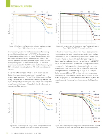
            Figure 9(a): Deflection profile along center line of overhang [M-line in   Figure 9(b): Deflection profile along center line of overhang [M-line in
                      Figure 5(a)] in the unstrengthened state             Figure 5(a)] in the NSM FRP-strengthened state

           It is noteworthy that removal of loose concrete after testing   It should be noted that position 2 [see Figure 5(a)] represents a
           showed that bond between the NSM FRP and concrete was   location above the outer stem of the box-girder and therefore
           largely maintained except in the area of diagonal cracking in   represents the end of the overhang. In all cases, it is seen that
           the concrete [Figure 8(b)] in a manner similar to that of the   there is virtually no discernable deflection past this point. In
           as-built specimen but at a significantly higher load due to the   both cases (center line and edge), the addition of the NSM FRP
           strengthening action of the NSM FRP strips. The maximum   strips results in a decrease in deflection at comparable loads as
           strain value recorded in the CFRP strips at ultimate capacity was   measured by the two potentiometers closest to the overhang
           3846 microstrain indicating that the FRP itself was not close to
           rupture.                                               edge [points 3 and 4 in Figure 5(a)] with the deflections in the
                                                                  strengthened case as shown in Figure 10(b), as an example
           It is of interest to compare deflection profiles as measured   being between 68% and 78% of those in the unstrengthened
           by the linear potentiometers between the as-built and   case in Figure 10(a). The effectiveness of the NSM FRP strips is
           strengthened specimens. Figures 9(a) and (b) compare profiles   further highlighted by the fact that the deflection away from the
           along the center line of the specimen denoted by line M in the   edge is lower in the strengthened case even at the higher load
           layout in Figure 5(a), while Figures 10(a) and (b) compare profiles   levels.
           along line A in the layout in Figure 5(a) which is adjacent to an
           outer edge of the specimen.


                A1                      A2        A3   A4              A1                       A2      A3    A4
              0                                                       0
                                                         24 kN                                                  24 kN
               1                                                      1
                                                                                                                60 kN
              2                                           60 kN       2
                                                                                                                84 kN
              3                                           84 kN       3                                         116 kN
            Deflection (mm)  4 5                          102 kN    Deflection (mm)  4 5                          136 kN


                                                         114 kN
                                                                                                                160 kN
              6
               7                                                      6 7
              8                                                       8
                                                                                                                184 kN
              9                                                       9
                                                                                                                196 kN
              10                                                     10
             Figure 10(a): Deflection profile along a line of linear potentiometers   Figure 10(b): Deflection profile along a line of linear potentiometers adjacent
                adjacent to the edge of the unstrengthened test specimen  to the edge of the test specimen in the NSM FRP-strengthened state


        16    THE INDIAN CONCRETE JOURNAL | JUNE 2021
   7   8   9   10   11   12   13   14   15   16