
Page 5 - June-Month
P. 5
TECHNICAL PAPER
designers” . Other similar guidelines are provided by Wassef 2. SPECIMENS AND TEST CONFIGURATION
[9]
et al. [10] and AASHTO . Of special import is the rehabilitation
[11]
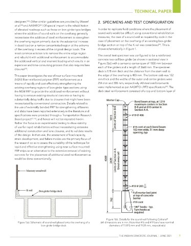
of elevated roadways such as those on box-girder type bridges In order to replicate field conditions where the placement of
where the addition of sound walls on the overhang generally sound walls would be difficult using conventional rehabilitation
necessitates the addition of steel reinforcement to strengthen measures, the case of a sound wall as required by code in the
the overhang region primarily due to the substantial increase case of placement on the overhang of an existing box-girder
[9]
in dead-load on a narrow concentrated region at the extreme bridge section on top of the K-rail was considered . This is
of the overhang in excess of the original design loads. The shown schematically in Figure 1.
most common solution is to remove the entire edge region
and rebuild it with additional reinforcement to accommodate The overall test specimen was configured to be a reinforced
the additional vertical and moment loading which results in an concrete two-cell box-girder [as shown in sectional view in
expensive and time-consuming process that also requires lane Figure 2(a)] with a center-to-center span of 1830 mm between
closures . each of the girders and a length of 3660 mm. The specimen
[12]
deck is 178 mm thick and the distance from the stem wall to
This paper investigates the use of near surface mounted the edge of the overhang is 483 mm. The bottom slab was 152
(NSM) fiber-reinforced polymer (FRP) reinforcement as a mm thick and the widths of the outer and center girders were
means of rapidly and cost-effectively strengthening the 254 mm and 305 mm, respectively. All steel reinforcements
existing overhang regions of box-girder type sections using were implemented as per AASHTO-LRFD specifications . The
[15]
the NSM FRP to provide the additional reinforcement without deck steel reinforcement consisted of a top and bottom layer of
having to remove existing structural concrete or having to
substantially delay traffic due to closures that might have been
necessitated by conventional construction. Details related to
the use of externally bonded FRP for strengthening of beams
and slabs have been reported extensively in the literature and
specifications were provided through a Transportation Research
Board project [13, 14] , and hence will not be repeated herein.
Rather the focus is on experimental testing to show viability
of use for rapid rehabilitation without necessitating extensive
additional construction and lane closures, and to validate results
of the design. In that vein, the assessment of load capacity,
strain development, and failure modes are the primary focus of
the research so as to assess the suitability of the technique for
rapid and effective strengthening using near surface mounted
FRP strips as an alternative to the extensive removal of existing
concrete for the placement of additional steel reinforcement as
would be done conventionally.
Figure 1(b): Details for the sound wall following Caltrans [9]
Figure 1(a): Schematic of sound wall placed onto the overhang of a (All dimensions are in mm. Note that #16 and #19 bars have nominal
box-girder bridge deck diameters of 15.875 mm and 19.05 mm, respectively)
THE INDIAN CONCRETE JOURNAL | JUNE 2021 9