
Page 7 - June-2022
P. 7
TECHNICAL PAPER
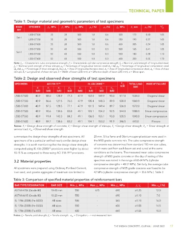
Table 1: Design material and geometric parameters of test specimens
BEAM SPECIMEN f ck , MPa f ' c , MPa f yl , MPa ρ st ( %) ρ cs (%) f yv , MPa S v , mm ρ sv (%) a / d
SET
L500-ST500 35 28 500 1.8 0.6 500 170 0.40 1.05
Set-I
L500-ST550 35 28 500 1.8 0.6 550 190 0.37 1.05
L500-ST600 35 28 500 1.8 0.6 600 205 0.34 1.05
L550-ST500 50 40 550 1.8 0.3 500 165 0.41 1.05
Set-II
L550-ST550 50 40 550 1.8 0.3 550 180 0.38 1.10
L550-ST600 50 40 550 1.8 0.3 600 200 0.35 1.70
Note: f ck = Characteristic cube compressive strength; f ' c = Characteristic cylinder compressive strength; f yl = Nominal yield strength of longitudinal steel;
f yv = Nominal yield strength of shear stirrups; ρ st = Percentage of longitudinal tension steel (A st / bd); ρ sc = Percentage of longitudinal compression steel
(A sc /bd); ρ sv = Percentage of shear stirrups (A sv /bs v ); A st = Area of longitudinal tension steel; A sc = Area of longitudinal compression steel; A sv = Area of shear
stirrups; S v = Longitudinal of shear stirrups; b = Width of beam (230 mm); d = Effective depth of beam (255 mm); a = Shear span.
Table 2: Design and observed shear strengths of test specimens
SPECIMENS ACI 318-19 [3] IS: 456 (2000) [2] V exp TOTAL LOAD MODE OF FAILURE
(kN) (kN)
V c V s V n V ns V c V s V n V ns
(kN) (kN) (kN) (kN) (kN) (kN) (kN) (kN)
L500-ST500 40.9 88.0 128.9 77.3 47.9 102.0 149.9 90.0 517.0 1034.0 Diagonal shear
L500-ST550 40.9 86.6 127.5 76.5 47.9 100.4 148.3 89.0 530.0 1060.0 Diagonal shear
L500-ST600 40.9 87.5 128.5 77.1 47.9 101.5 149.4 89.7 536.0 1072.0 Diagonal shear
L550-ST500 48.9 90.6 139.6 83.8 49.1 105.1 154.2 92.5 544.0 1088.0 Shear-compression
L550-ST550 48.9 91.4 140.3 84.2 49.1 106.0 155.1 93.0 520.5 1040.0 Shear-compression
L550-ST600 48.9 89.7 138.6 83.2 49.1 104.1 153.2 91.9 346.5 693.0 Flexure
Notes: V c = Design shear strength of concrete; V s = Design shear strength of stirrups; V n =Design shear strength; V ns = Shear strength at
service load; V exp =Observed shear strength
summarizes the design shear strengths of test specimens. All 20 mm. Silica fume and Glenium super-plasticizer were used in
specimens of in a particular set had nearly similar design shear the M50 grade concrete mix. The cube compressive strength
strengths. It is worth mentioning that the design shear strengths of concrete was determined from standard 150 mm size cubes,
computed using IS: 456 (2000) provisions were higher by about which were cast from each beam set and cured at the same
[2]
10-15 % as compared to those using ACI 318-19 provisions. conditions as the beams. The measured mean cube compressive
[3]
strength of M50 grade concrete on the day of testing of the
3.2 Material properties specimen was noted in the range of 60-64 MPa (cylinder
compressive strengths = 48-51 MPa). Similarly, the average cube
All specimens were prepared using Ordinary Portland Cement, compressive strength of M35 grade concrete was found to be
river sand, and granite aggregate of maximum size limited to 42 MPa (cylinder compressive strength = 33.6 MPa ). Table 3
Table 3: Comparison of specified material properties of reinforcement bars
BAR TYPE/DESIGNATION BAR SIZE Min. f y , MPa Max. f y , MPa Min. f u , MPa f u / f y Min. ε su ( %)
ASTM A706 (Grade 80) 10-20 mm 550 675 690 ≥1.25 12.0
ASTM A615 (Grade 80) 10-20 mm 550 - 690 ≥1.10 7.0
IS: 1786 (2008) (Fe-500D) All sizes 500 - 565 ≥1.10 16.0
IS: 1786 (2008) (Fe-550D) All sizes 550 - 600 ≥1.08 14.5
IS: 1786 (2008) (Fe-600) All sizes 600 - 660 ≥1.06 10.0
Notes: f y = Tensile yield strength; f u = Tensile strength; ε su = Elongation; – = not measured item
THE INDIAN CONCRETE JOURNAL | JUNE 2022 17