
Page 10 - Open-Access-May-2020
P. 10
TECHNICAL PAPER
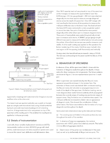
Load-control mechanism One 100 T capacity load cell was placed on top of the specimen
with display panel and at the mid-span, to measure the applied lateral load. Two
pendulum gauge
Testing machine LVDTs (range: ±10 mm; gauge length = 283 mm) were attached
diagonally at one shear span to measure average diagonal
Specimen supportd on
pedestal strains across the depth of a specimen. One LVDT (range: ±25
Data acquisition system mm) was fixed at the bottom of the specimen to measure the
mid-span deflection due to the lateral load. The load cell and
the three LVDTs were connected to a data acquisition system
to record the data. Two pairs of steel pellets were pasted
diagonally at the other shear span to measure diagonal strains.
Three pairs of steel pellets were pasted longitudinally at mid-
span to measure axial strains. A DEMEC gauge (gauge length:
200 mm) was used to measure the deformations manually across
the pellets. A hand-held microscope was used to measure crack
widths. A white-wash coating was applied on the specimen for
better monitoring of the cracks. Grid lines were marked in the
(a)
test region at 50 mm spacing, both horizontally and vertically.
Lateral load
During a test, the lateral load was increased in steps of 10 kN.
The test was continued up to the peak load till the failure of the
Loading arm
specimen.
Load cell
6. BEHAVIOUR OF SPECIMENS
Specimen
In absence of ties, all the specimens failed in shear with the
Roller support Hinge support
formation of diagonal cracks throughout the depths. A truss
action for shear resistance did not generate. The failure patterns
Supporting
1000 mm longitudinal are shown in Figure 7, for one representative specimen in each
girder pair.
Supporting cross girder
When a specimen was loaded laterally, thin flexural cracks
Test floor appeared around the mid-span in the tension face. The
(b) extension of these cracks was limited. With continued loading,
the flexural cracks did not widen or propagate beyond one-
Figure 6: Details of experimental set-up (a) Overall photograph and
(b) Schematic sketch tenth of the depth of the specimen. On further loading, one or
more diagonal shear cracks formed suddenly which propagated
between the outside edges of loading area and inside edges of
supported on bearings with restrained roller (hinge) at one end support areas. They formed at one or both the shear spans. The
and free roller at the other end. mid-span deflection increased at a faster rate on appearance
of diagonal cracks. This showed the contribution of shear
The lateral load was applied vertically over a patch at the mid-
span as a single point monotonic load, using a load-controlled deformation. The failure was marked at the formation of a major
hydraulic jack and cross beam (loading arm) of a bending diagonal crack throughout the depth.
machine. A hinge restrained roller was present on top of the Some prominent observations during the tests were as follows:
specimen at the loading point. This enabled the loading to be
applied at mid-span precisely. (a) The cracking was not limited in the jacket portion, but was
throughout the width of the member.
5.2 Details of Instrumentation (b) In absence of large size aggregates, the cracks in
specimens with HSSCC jacket were relatively smooth. This led to
Load cells, linear variable displacement transducers (LVDTs), minimal effect of aggregate interlock.
demountable mechanical strain (DEMEC) gauge with steel
pellets, crack microscope and data acquisition system were used (c) Delamination of the jacket was not detected till the peak
to record the lateral load, deflection and deformation data. load, as well as by deliberately drilling at various spots. This
The IndIan ConCreTe Journal | MaY 2020 11