
Page 15 - June-2022
P. 15
TECHNICAL PAPER
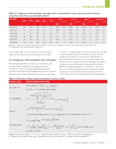
Table 4: Comparison observed shear strengths with code predicted values using measured material
properties and without partial-safety factors
SPECIMEN f ckm f ' c f ym θ V exp IS:456 [2] ACI 318 [3] Sahoo [23] CSA A23.3 [24]
f '
(MPa) (MPa) (MPa) (Deg.) √ c bd
V u V exp / V u V u V exp / V u V u V exp / V u V u V exp / V u
(kN) (kN) (kN) (kN)
L500-ST500 42 33.6 540 54.0 1.53 185.2 2.8 185.9 2.8 200.3 2.6 159.2 3.2
L500-ST550 42 33.6 580 46.1 1.56 180.2 2.9 180.9 2.9 195.3 2.7 154.3 3.4
L500-ST600 42 33.6 620 44.1 1.58 179.1 3.0 179.8 3.0 194.2 2.8 153.2 3.5
L550-ST500 60 48.0 540 45.3 1.34 191.6 2.8 201.2 2.7 213.4 2.5 162.1 3.4
L550-ST550 60 48.0 580 42.1 1.29 189.5 2.7 199.2 2.6 211.4 2.5 162.1 3.2
L550-ST600 64 51.2 620 34.0 0.83 185.1 1.9 196.6 1.8 208.3 1.7 173.4 2.0
Notes: f ckm = Measured mean cube compressive strength of concrete; f ' cm = Estimated mean cylinder compressive strength of concrete;
f ysm = Measured mean tensile strength of steel stirrup
current codes. This, in turn, resulted in an increased shear in Table 5 . In all these design standards, the total shear strength
resistance contribution of transverse stirrups in the beams. (V u ) of a concrete member is considered as the sum of shear
resistance of concrete, V c and transverse reinforcement, V s .
[3]
5.3 Comparison with predicted shear strengths Both ACI 318-19 and Sahoo [23] utilize Constant-angle Truss
Theory for the computation of the shear strengths of concrete
The measured peak shear strengths, V exp of specimens were members, whereas the Modified Compression Field Theory
compared with the predictions using the provisions of (MCFT) [25] has been adopted in the CSA code [24] . The values
ACI 318-19 code, the Canadian Standards Association of V c and V s for the test specimens were computed using the
[3]
[2]
(CSA A23.3-04) code [24] , IS: 456 (2000) and Sahoo [23] . The shear measured material properties. Table 4 summarizes the ratio
design provisions of these referred documents are summarized of the measured maximum shear loads to the predicted shear
Table 5: Summary of shear design provisions in various codes
DESIGN CODE DESIGN SHEAR EQUATIONS
V = 0.16φλ ρ ) 1/3 f bd ; V = φ A f d
′
sv yv
c
( st
c
ACI 318-19 [3] s s
v
λ =
φ 0.75; = 1.0 (Normal-weight concrete)
0.85 f ′ c 1 5 + 6.89ρ f ′ − 1
c
IS: 456 (2000) [2] V = st bd ; V = 0.87A f d
c
s
sv yv
c
6 f ′ s v
6.89ρ
st
0.36λλ λ ρ f ) 1/3 d
( st ck
V = a g s bd ; V = 0.87A f
sv yv
s
c
Sahoo [23] γ m s v
γ
λ = 1.0 (Normal-weight concrete) ; λ = 1.0 (d<400 mm) λ = 0.83 (Rectangular section) ; m = 1.5
g
a
s
d v cot θ
V =
φ
A f
′
V = φβ f bd v ; s s sv yv s v
λ
c
c
c
CSA A23.3-04 [24] 0.4 1300 (M d ) V+ 35
o
β = ; ε = ud v ud ; k gd = ; θ = 29 7000ε ≥ 30 ;
+
+
+
1 1500ε x 1000 kd + gd v x ( 2 E A ) 16 a ge x
ss
φ c 0.65; φ = s = 0.85
Notes: Total shear strength, V u = V c + V s ; θ = Angle of diagonal shear crack; a ge = Effective size of coarse aggregate;
d v = Effective shear depth (≈0.9d ); M ud = Design bending moment demand; V ud = Design shear force demand
THE INDIAN CONCRETE JOURNAL | JUNE 2022 25