
Page 13 - June-Month
P. 13
TECHNICAL PAPER
4000 4000
24 kN 196 kN
3500 3500
60 kN
3000 84 kN 3000 196 kN
184 kN
Strain (microstrain) 2500 116 kN Strain (microstrain) 2500 136 kN
160 kN
116 kN
2000
2000
136 kN
1500
1500
184 kN
1000 160 kN 1000 84 kN
60 kN
196 kN
500 500
24 kN 24 kN
0 0
G F E D C B A 1B 2B 3B 4B 5B 6B 7B 8B 9B
Gauge Location Strain Gage Position
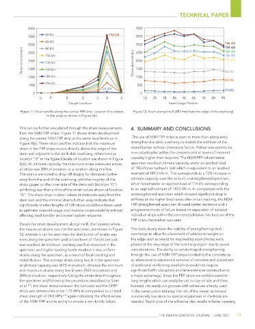
Figure 11: Strain profile along the central FRP strip. Location A is closest Figure 12: Strain along line B (483 mm from the edge of the overhang)
to the edge as shown in Figure 5(b)
This can be further elucidated through the strain measurements 4. SUMMARY AND CONCLUSIONS
from the NSM FRP strips. Figure 11 shows strain development
along the central NSM FRP strip at the same load levels as in The use of NSM FRP strips is seen to more than adequately
Figure 9(b). These strain profiles indicate that the maximum strengthen the deck overhang to enable the addition of the
strain in the FRP strips occurs directly above the edge of the sound barrier without premature failure. Failure was seen to be
stem wall adjacent to the deck slab overhang, referenced as non-catastrophic within the concrete and at levels of moment
location “B” in the figure [details of location are shown in Figure capacity higher than required. The NSM FRP-rehabilitated
5(b)]. At ultimate capacity, the maximum strain measured across specimen reached ultimate capacity under an applied load
all strips was 3846 microstrain at a location along this line. of 196 kN per hydraulic jack which is equivalent to an applied
The strains are noted to drop off sharply for distances further moment of 189.2 kN-m. This corresponds to a 72% increase in
away from the end of the overhang, with the majority of the ultimate capacity over the as-built unstrengthened specimen,
strain gages on the inner side of the stem wall (location “C”) which failed under an applied load of 114 kN corresponding
exhibiting less than a third of the strain values shown at location to an applied moment of 110.0 kN-m. In comparison with the
“B”. The sharp drop in strain values at distances away from the unstrengthened specimen which showed significant drop in
stem wall and the minimal strains further away indicate that stiffness at the higher load levels after initial cracking, the NSM
significantly shorter lengths of FRP strips could have been used FRP-strengthened specimen showed better resilience and a
to optimize material usage and improve constructability without progressive mode of failure based on separation of isolated
affecting load transfer and overall system response. individual strips within the concrete/adhesive. No fracture of the
FRP strips themselves was seen.
Details for strain development along line B, the location where
the maximum strains occur in the specimen, are shown in Figure The tests clearly show the viability of strengthening deck
12, wherein it can be seen that the distribution of strains was overhangs to allow for placement of additional weight on
even along the specimen until a load level of 116 kN per jack the edge such as would be required by sound/noise walls
was reached. At this level, cracking was first observed in the placed at the very edge of the overhang region due to space
specimen and higher loading levels resulted in less uniform considerations. The ability to conduct rapid strengthening
strains along the specimen, as a result of local cracking and through the use of NSM FRP strips bonded to the concrete as
redistribution. The average strain along line B in the specimen an alternative to substantial removal of concrete and placement
at ultimate capacity was 3423 microstrain, whereas the minimum of additional reinforcing steel which would not require
and maximum strains along line B were 2943 microstrain and significant traffic disruption and time intensive construction is
3846 microstrain, respectively. Using the strain data throughout a major advantage. Since the FRP strips are prefabricated in
the specimen and following the procedure described by Siem long lengths which can easily be cut to size on site and then
et al. [21] , the shear stress between the concrete and the CFRP bonded into easily cut grooves with adhesives already used
strips was determined to be 1.75 MPa in comparison to a listed in the construction industry, the risk of the newer technique
shear strength of 24.8 MPa [22] again indicating the effectiveness is extremely low since no special equipment or methods are
of the NSM FRP and its ability to ensure a non-brittle failure. needed. Rapid cure of the adhesive also results in faster opening
THE INDIAN CONCRETE JOURNAL | JUNE 2021 17