
Page 6 - Open-Access-May-2020
P. 6
TECHNICAL PAPER
of fibres or their lumping. Hence, the jacket concrete shall The specimens were intentionally designed to fail in shear
preferably be without fibres. No study was reported comparing before and after jacketing, by maintaining adequate flexural
the performances of members with normal-strength and capacity and limited shear span-to-effective depth (a/d) ratio
high-strength SCC in the jacket. The study reported in this equal to 1.7. The shear span ‘a’ was measured between the
paper compares the behaviour of strengthened RC beam- edges of the loading and support plates. The effective depth ‘d’
column specimens, using a HSSCC and a NSSCC as jacketing for the longitudinal tension reinforcement of a jacketed section
materials without fibres. The selected specimens were shear- was computed considering the weighted area average of the
critical, showing failure generated by diagonal shear cracks on effective depths of the inner and jacket portions. The areas
the application of lateral load. The test details and results are of longitudinal tension reinforcement in the inner and jacket
presented further. portions were used as weighting factors for averaging.
Twelve jacketed specimens with rectangular cross-section were
4. DETAILS OF SPECIMENS tested. Out of them, six were jacketed with HSSCC and other
six were jacketed with NSSCC. These specimens were designed
The particulars of specimen geometry, preparation of concrete,
reinforcing steel and preparation of specimen are presented in without ties, to study the concrete contribution and dowel action
this section. for the shear failure caused by diagonal cracking through the
depth of each specimen. In the conventional capacity-based
approach of retrofit, a shear-critical member is converted into a
4.1 Specimen Geometry flexure-critical one after jacketing. However, the objective of the
present study was to examine the behaviour under shear even
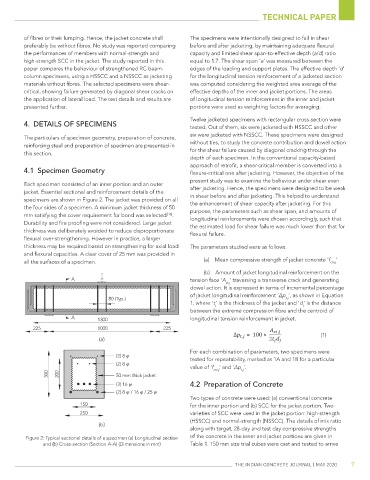
Each specimen consisted of an inner portion and an outer
jacket. Essential sectional and reinforcement details of the after jacketing. Hence, the specimens were designed to be weak
specimens are shown in Figure 2. The jacket was provided on all in shear before and after jacketing. This helped to understand
the enhancement of shear capacity after jacketing. For this
the four sides of a specimen. A minimum jacket thickness of 50 purpose, the parameters such as shear span, and amounts of
mm satisfying the cover requirement for bond was selected [16] . longitudinal reinforcements were chosen accordingly, such that
Durability and fire proofing were not considered. Large jacket the estimated load for shear failure was much lower than that for
thickness was deliberately avoided to reduce disproportionate flexural failure.
flexural over-strengthening. However in practice, a larger
thickness may be required based on strengthening for axial load The parameters studied were as follows.
and flexural capacities. A clear cover of 25 mm was provided in
all the surfaces of a specimen. (a) Mean compressive strength of jacket concrete ‘f cm,j ’
(b) Amount of jacket longitudinal reinforcement on the
A tension face ‘A ’ traversing a transverse crack and generating
st,j
dowel action. It is expressed in terms of incremental percentage
of jacket longitudinal reinforcement ‘∆p ’, as shown in Equation
80 (Typ.) t,j
1, where ‘t’ is the thickness of the jacket and ‘d’ is the distance
j j
between the extreme compression fibre and the centroid of
A 1300 longitudinal tension reinforcement in jacket.
225 1000 225
, (1)
(a) , 2
For each combination of parameters, two specimens were
(2) 8 φ tested for repeatability, marked as 1A and 1B for a particular
(2) 8 φ
value of ‘f cm,j ’ and ‘∆p ’.
t,j
300 200 50 mm thick jacket
(3) 16 φ 4.2 Preparation of Concrete
(2) 8 φ / 16 φ / 25 φ
Two types of concrete were used: (a) conventional concrete
150 for the inner portion and (b) SCC for the jacket portion. Two
250 varieties of SCC were used in the jacket portion: high-strength
(HSSCC) and normal-strength (NSSCC). The details of mix ratio
(b)
along with target, 28-day and test day compressive strengths
Figure 2: Typical sectional details of a specimen (a) Longitudinal section of the concrete in the inner and jacket portions are given in
and (b) Cross-section (Section A-A) (Dimensions in mm) Table 1. 150 mm size trial cubes were cast and tested to arrive
The IndIan ConCreTe Journal | MaY 2020 7